For safety reasons, the electrical equipment is not directly connected to high-voltage meters or control equipment. When connecting electrical instruments to measuring equipment, transformers such as voltage transformers and current transformers are used to lower the voltage and current from high to low values that can be measured by standard instruments.
Table of Contents
What is a voltage transformer used for?
Voltage transformers are tools used to step down and lower a system’s voltage to a level that is regarded as safe. It works by enabling energy meters to keep an eye on how electrical connections are functioning, which may require a higher voltage than usual to do so.
If you’re going somewhere with a higher power standard than what your appliances use, you’ll need a step-down voltage converter. On the other hand, bringing 220-110 volt equipment to the U.S. or Canada necessitates the use of a step-up voltage converter that can raise 110-120 volts to 220-240 volts.
On a larger scale, one of the most important components in the creation of electricity is the transformers. It provides a vital connection between two circuits which transformers have simplified this approach.
What are the two types of voltage transformers?
Types of voltage transformers based on function
1.Metering type voltage transformers
Measuring instruments like voltmeters, ammeters, and kilowatt-hour meters are used with metering current transformers (CTs) to: Isolate the instruments from the power circuits; Standardize the instruments, often at 5 amps or 1 amp
2.Protection-type voltage transformers
For isolation and protection from high voltages during tests, protection-type potential transformers are commonly utilized. These transformers have electrically segregated windings, and the low voltage and high voltage sides are not joined directly.
The types of voltage transformers can further be classified into three based on their operating voltage, and they are as follows:
1.High-voltage voltage transformers
High voltage transformers convert voltages, typically from higher to lower, from one level or phase arrangement to another. They may have features for applications, including electrical isolation, power distribution, and control and instrumentation.
2. Medium-voltage voltage transformers
Transformers with a voltage range of 2 kV to 35 kV are referred to as medium voltage transformers. The distribution transformers frequently operate in this voltage range, which normally qualifies them as medium voltage types.
3. Low-voltage voltage transformers
Every system of outdoor lighting is constructed around a low voltage transformer. It converts the 120-volt current into a low voltage current – between 12-15 VAC. The efficiency of its conversion determines how well the transformer regulates the voltage output and how much energy is expended in the process.
In addition, the types of voltage transformers may also be classified according to their construction.
Based on how they are built, potential transformers can be classified as either capacitor voltage type or wound type.
1.Wound-type potential transformer
Potential transformers of the shell and core types are categorized as wound-type. On the core limbs, the primary and secondary windings are wound with the appropriate insulation. The structure becomes complicated for measuring high voltages (usually greater than 10 kV) due to insulation factors. Considering that, the next item is commonly used to measure higher voltages.
2.Capacitive potential transformer
A capacitive divider and an auxiliary transformer are used in a capacitive potential transformer. The need for a high-rated potential transformer is removed by the capacitor divider.
Why do we need a transformer?
Transformers are used for a wide range of functions, including raising the voltage from electric generators to enable long-distance transmission of electricity and lowering the voltage of conventional power circuits to run low-voltage devices like doorbells and toy electric trains.
What are the 16 types of transformers?
A transformer is a power transmission tool that moves electrical energy between electrical circuits or between several circuits at once. In order to put it another way, it is a voltage-controlling device that is frequently employed in the transmission and distribution of AC electricity.
Applications for electronic and electric power use a variety of transformer sizes and types, and they are as follows:
- Step-down transformer – A step-down transformer reduces the output voltage by converting high voltage from the primary side to a lower voltage on the secondary coil.
- Step-up transformer – Low voltage from the transformer’s primary side can be transformed into a high voltage on the secondary side by a step-up transformer.
- Single-phase transformer – Power transformers that use single-phase alternating current, or single-phase AC, rely on voltage cycles that work in integrated time phases. These transformers are known as single-phase transformers.
- Three-phase transformer – Electricity is produced and distributed using three-phase transformers in accordance with power consumption.
- Power transformer – Without altering its frequency, power can be transferred from one circuit to another using a power transformer.
- Distribution transformer – Similar to step-down transformers, distribution transformers reduce high grid voltage to the level needed by the final consumer.
- Current transformer – Alternating current can frequently be increased or decreased by using current transformers (AC).
- Isolation transformer – This sort of transformer is used to transfer electrical power from an alternating current while isolating the powered equipment for safety concerns.
- Potential transformer – To lower voltage levels, potential transformers or voltage transformers are frequently utilized.
- Instrument transformer – Electrical parameters like current, voltage, power, frequency, and power factor are measured using these transformers. To safeguard the electrical system, the instrument transformer has to incorporate a relay.
- Air Core transformer – The primary and secondary windings of this transformer are both mounted on a non-magnetic stripe. Both of the windings through the air have flux linkage. Low mutual inductance in the air-core indicates that the air medium has a strong resistance to accepting the generated flux.
- Iron core transformer – This style features several soft iron plates on which the primary and secondary windings are mounted, creating the perfect connection to the flux. Due to the conductive and magnetic qualities of iron, it offers less resistance to coupling flux than the air core.
- Ferrite core transformer – Power transformer windings and other components are formed on a ferrite magnetic core that is used in this type of transformer. Due to their high magnetic permeability, ferrite cores are employed in high-frequency systems like switch-mode power supplies.
- Toroidal core transformers – They are passive electrical components that have a wire looped around a magnetic core in the form of a circle made of ferromagnetic material.
- Autotransformer – These transformers’ primary and secondary windings share a single winding. There are three taps on the autotransformer winding where the electrical connections are made.
- Grounding or earthing transformer – It is a three-phase electric power system’s ground path or neutral provided by an underground WYE or delta-connected system. This may aid in lowering voltage transients that result from ground faults.
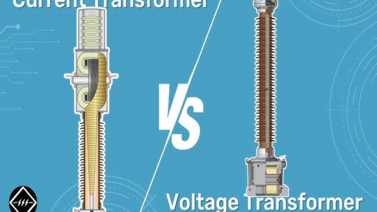
What is the difference between current and voltage transformer?
The voltage and current transformers differ in a number of different ways.
One of the biggest differences between them is that the voltage or potential transformer transforms high voltage into low voltage while the current transformer transforms high current into the low current.
| Basis for Comparison | Current Transformer | Voltage or Potential Transformer |
| Definition | Transforms the current from high value to low value. | Transforms the voltage from high value to low value. |
| Core | Commonly built up with lamination of silicon steel. | It is made of high-quality steel that operates at lower flux densities. |
| Primary Winding | Carries the current to be measured | Carries the voltage to be measured |
| Secondary Winding | Connected to the instrument’s current winding | Connected to the meter or instrument |
| Connection | Connected in series with the instrument | Connected in parallel with the instrument. |
| Primary Circuit | Has fewer or smaller number of coils | Has more or larger number of coils |
| Secondary Circuit | Has a large number of coils and cannot be open circuit. | Has a small number of coils and can be an open circuit. |
| Range | From 5A to 1A | 110v |
| Transformation Ratio | High Transformation Ratio | Low Transformation Ratio |
| Burden | Does not depend on the secondary burden | Depends on the secondary burden |
| Input | Has constant current | Has constant voltage |
| Full line current | The primary winding consists of the full line current. | The primary winding consists of the full line voltage. |
| Types | Two types
|
Two types
|
| Impedance | Low Impedance | High Impedance |
| Applications | For measuring current and power, monitoring the power grid operation, for operating a protective relay | For Measurement, power source, operating protective relay. |
Due to the magnetic circuit being present in both the main and secondary winding of the current and potential transformers, their design is comparable. But their approaches to working differ.
Here are some key points of their differences:
- The primary winding of a current transformer depends on the current flowing through the primary windings rather than the load on the secondary winding of the transformer, whereas the primary of a potential transformer depends on the load on the secondary winding.
- While the potential transformer’s input is constant voltages, the current transformer’s input is a constant current.
- The current transformer’s transformation ratio has consistently been high, whereas the potential transformer’s transformation ratio has consistently been low.
Remember that the ratio of the rated primary voltages to the rated secondary voltages is known as the transformation ratio of the current and voltages transformer.
- The standard voltages at the secondary winding of the potential transformer is up to 110V, whereas the normal range of the current transformer to measure the current is 5A or 1A.
- With so many spins, the secondary of the current transformer cannot be open-circuited when it is submerged in services. The potential transformer’s secondary winding has a limited number of turns and may be open circuit during the services.
- Current transformers have primary windings with few turns, whereas the primary winding of a potential transformer has many turns.
- The current to be measured is carried by the primary winding of the current transformer, whereas the voltages is carried by the primary of the potential transformer.
- Stainless steel laminations are used to construct the core of the current transformer. The potential transformer’s core is built of a high-performance core that operates at low flux densities.
- While the potential transformer is linked in parallel with the line, the primary winding of the current transformer is commonly connected in series with the transmission line whose current is to be measured.
- The potential transformer turns the high value of voltages into a low value, whereas the current transformer transforms the high value of current into a low value so that it may simply be measured by the instrument.
- In contrast to the potential transformer, which is used to detect high voltages current, the current transformer is primarily used to measure currents of such magnitude that they cannot be conveniently measured by a meter or other instrument.
- In contrast to the potential transformer, where the whole line voltages is directly linked to the primary terminal, the primary winding of the current transformer is directly connected to the full line current whose current is to be measured.
- Compared to the secondary winding, the transformer’s primary winding has a very low impedance, but the primary winding of a potential transformer has a high impedance. Note that the impedance, which is what happens when voltages is placed across a circuit, opposes the current that is given by that circuit.
In Summary,
Transformers help electricity systems be more reliable and efficient by adjusting voltages levels as needed in an electrical connection. They are utilized in numerous household, and commercial settings, but possibly their most crucial function is in the long-distance distribution and control of power.
It would be in your best interest to get in touch with the experts in planning your electrical projects involving components like transformers and other devices you might need. You may also visit www.se.com/th/en to get the most reliable electrical components from Schneider Electric, a trusted corporation that provides energy solutions with efficiency and sustainability.